|
 |
 |
 |
 |
 |
|
| GEOLOGY |
|
|
 |
 |
|
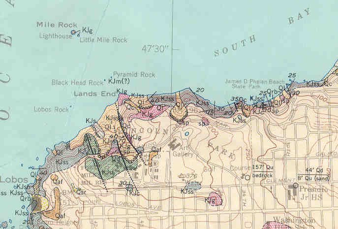
| Lincoln Park & Sea Cliff (USGS 1958) | Lincoln Park & Sea Cliff (USGS 1974) | |
 |
 |
|
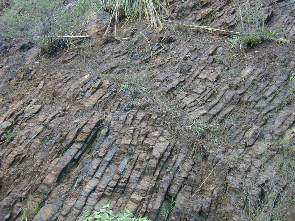
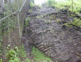
| Radiolarian Chert, typical N SF Quadrangle | Radiolarian Chert, exposed at site | |
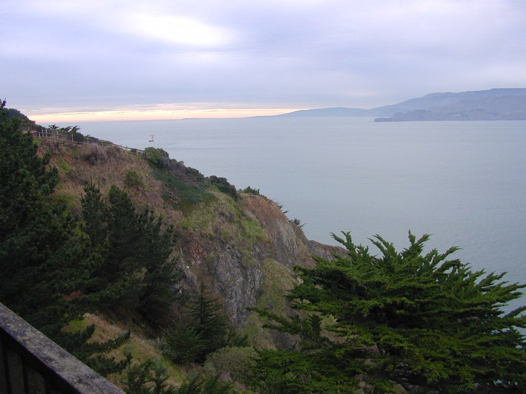
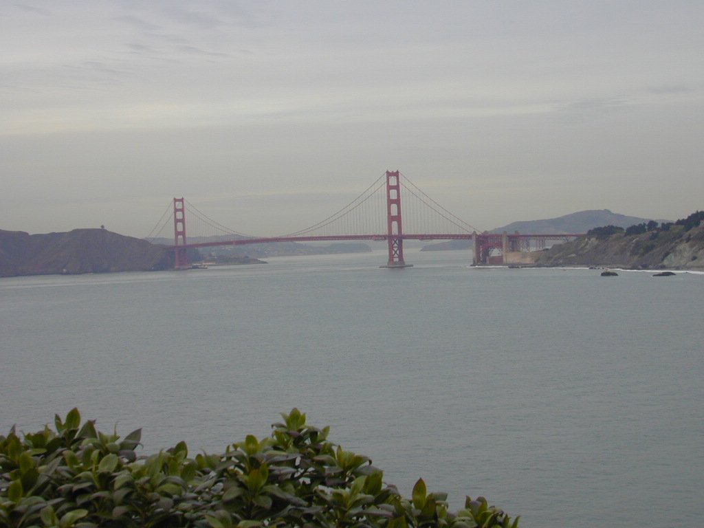
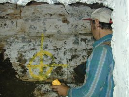
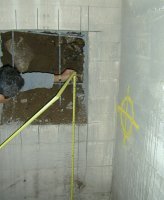
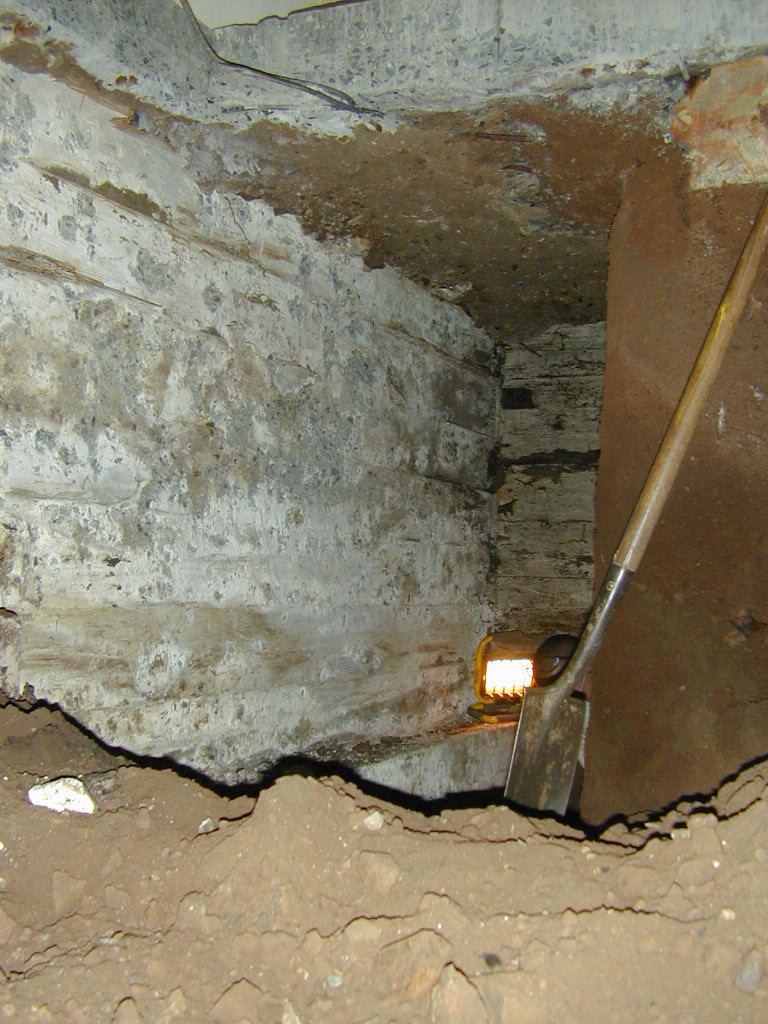
| Geologic Setting: The site is underlain with sedimentary bedrock of reddish-brown Radiolarian Chert [KJc], (observed) a prominent indurated rock type of the Franciscan formation, and Graywacke Sandstone [KJss] (observed and mapped, Schlocker 1974), a clastic sedimentary rock also Franciscan. Graywacke is thickbedded "dirty" sandstone; a poorly sorted mixture of angular and subangular grains ranging from fine to very coarse sand in size. The Franciscan Formation is Jurrassic and Lower & Upper Cretaceous age (Mesozoic; 144 to 208 million years old). |
|
|
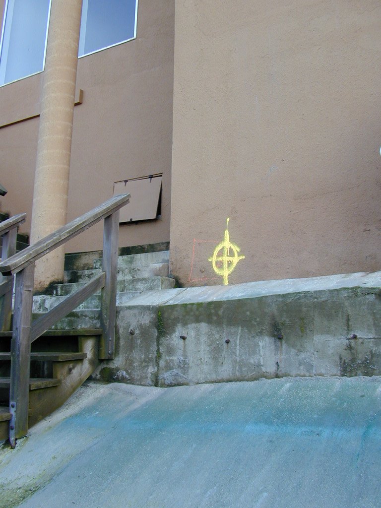
| Radiolarian Chert &
Graywacke Sandstone: Siliceous shale is generally interbedded with the chert (Bailey 1964). Radiolarian chert is exposed at Lincoln Park, immediately adjacent to the site (sandstone exposures also appear at some distance from the site). The chert is contorted (pinched and swelled); the ribbon layering of the chert beds has definite thin banded structures that are locally jointed and tightly folded with nearly horizontal axial folded planes. The chert is a very hard, compact, siliceous rock; the red pigmentation is caused by fine particles of ferric oxide; this sedimentary rock is believed to have been a colloidal gel formed by precipitation of silica (chalcedony and quartz enclosing skeletons and spicules of Radiolaria; Radiolaria appears in the red chert as tiny, colorless, spherical or bell-shaped masses) and small amounts of iron and aluminum oxides from sea water. Where exposed, the chert appears slight to moderately weathered. Slope stability in chert is generally good, however the bands of interbedded shale are susceptible to seepage and weathering. Over the chert, the slope is mantled with creep zones composed of colluvium. Colluvium is unconsolidated and unsorted soil material and weathered rock fragments accumulated on or at the base of the slope by natural gravitational or slope wash processes. |
| References
Bailey, Edgar H., Irwin, William P., & Jones, David L.,
1964; "Franciscan
and Related Rocks, and their Significance in the Schlocker, J., Bonilla, M. G., & Radbruch, D. H., 1958;
“Geology
of the San Francisco North Quadrangle, California”, Schlocker, Julius, 1974; "Geology of the San Francisco North
Quadrangle,
California", (includes Plates [1] "Geologic Map....", |
|
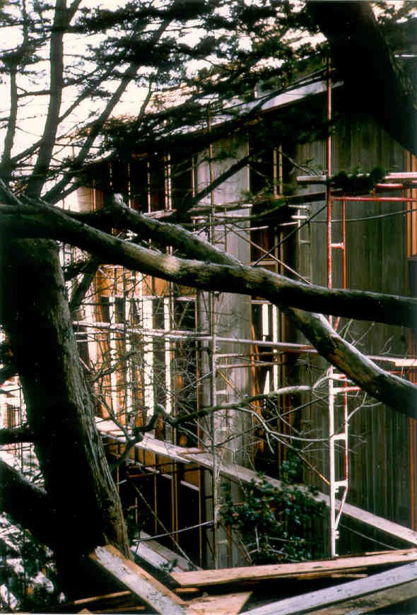
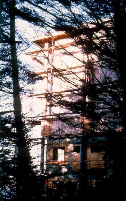
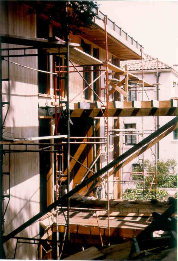
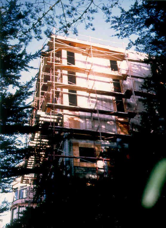
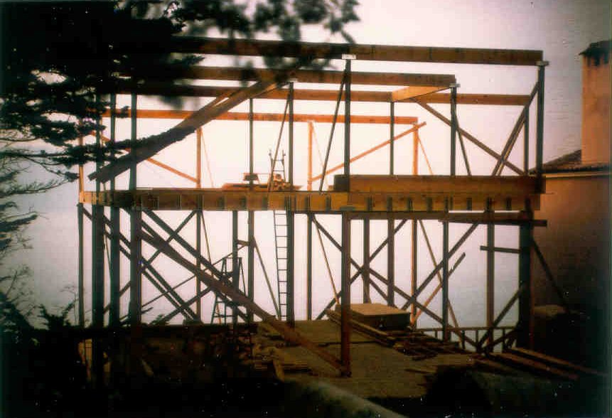
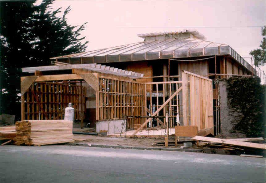
| 1964 Construction "Townhouse for Mr. & Mrs. Richard S. Bullis", designed by Kump Associates Architects, 1963. Photos during construction taken January, March, and April 1964. |
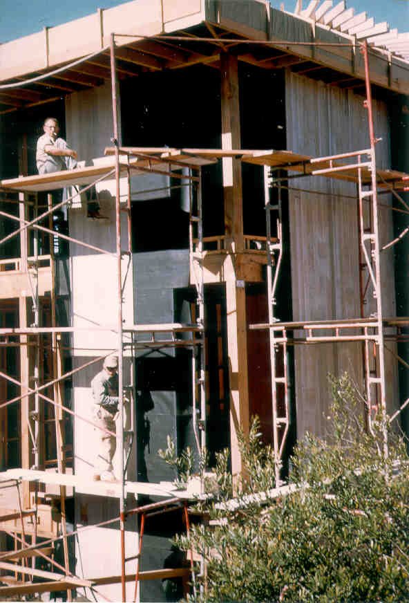 Northwest Corner (upper) |
 West Elevation (from street) |
 West Elevation (from park) |
 South Elevation (upper) |
 Partial South Elevation |
|
 |
 |
 |
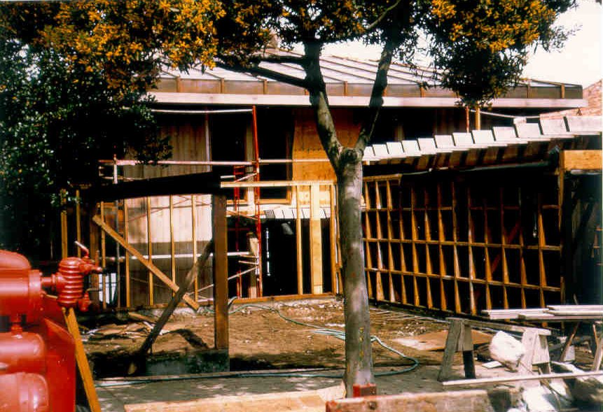
Left Image: Second (top) floor level before wall
framing Middle Image: Top floor framing, starting walls,
atrium
at right Right Image: North section framed first: |
|
 |
 |
 |
Left Image: Ballon framing, main and upper
floors, looking
north Middle Image: Right Image: |
|
 |
 |
Left Image: West garage
started, entry tramed Right Image: East garage started, |
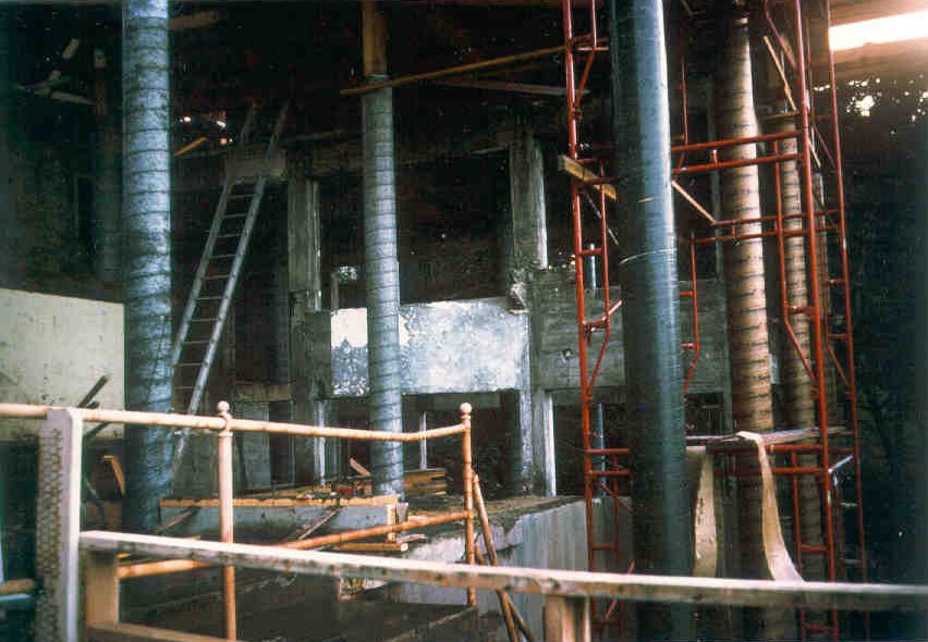
The 1964 Townhouse was built over the former three story addition to 880 El Camino del Mar designed by Bliss & Faville in 1921. The addition was partially demolished after 880 El Camino was subdivided into two lots. The lower floor was a "Laboratory" and a "Workroom". The middle floor had three "Servants Rooms, a Sewing Room, and a storeroom. The upper floor had two Dressing Rooms and a Bathroom at the western side and an elaborate Bedroom on the eastern side. |
|
 |
 |
 |
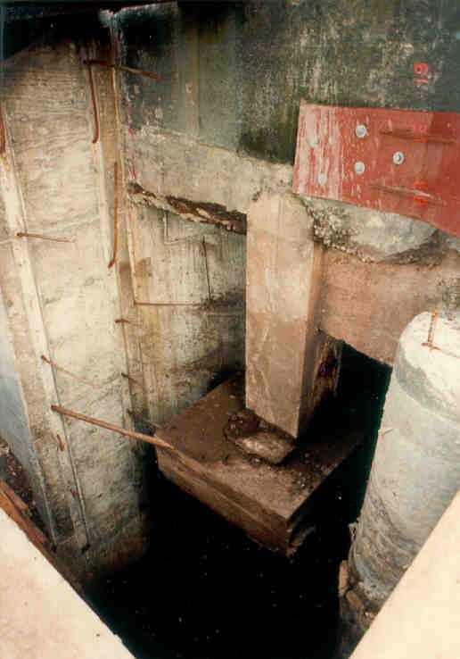 |
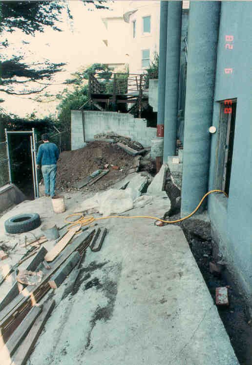
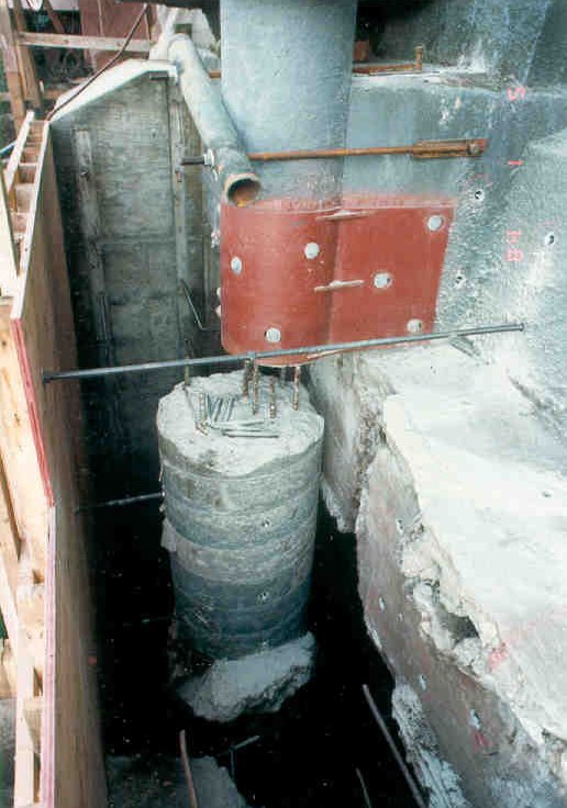
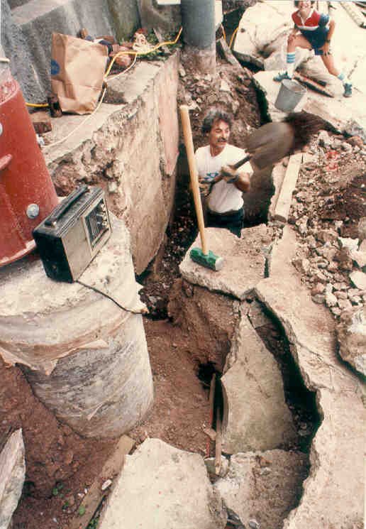
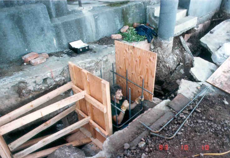
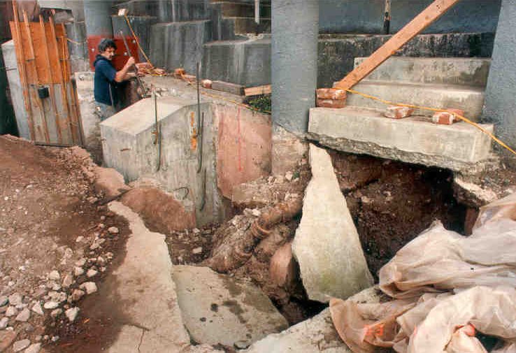
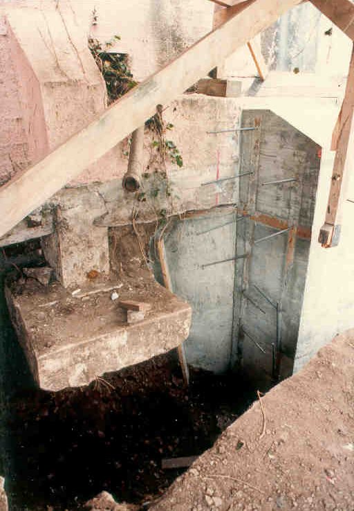
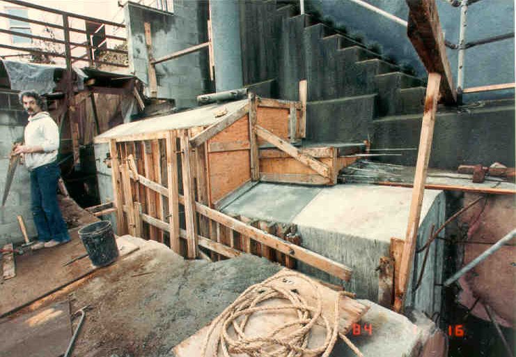
1983 Underpinning
Lower foundation support failed, pulling northeast concrete
column (sonotube
formed) at 890 Camino del Mar downhill and breaking it. Emergency repair was to pull the column back using a pipe and treaded rod anchors. Column was jacked to level upper stories which had sagged and then column was held in place with a steel bracket. 1941 underpinning was founded in loose soil rather than bedrock. |
 |
 |
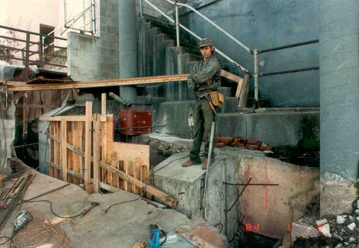 |
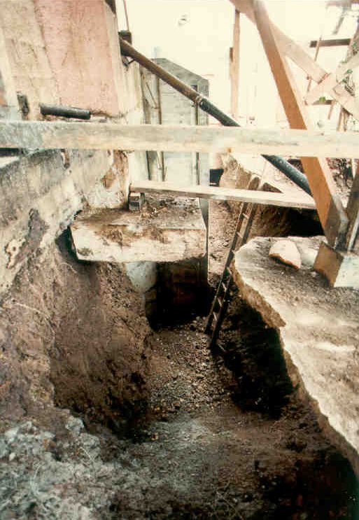
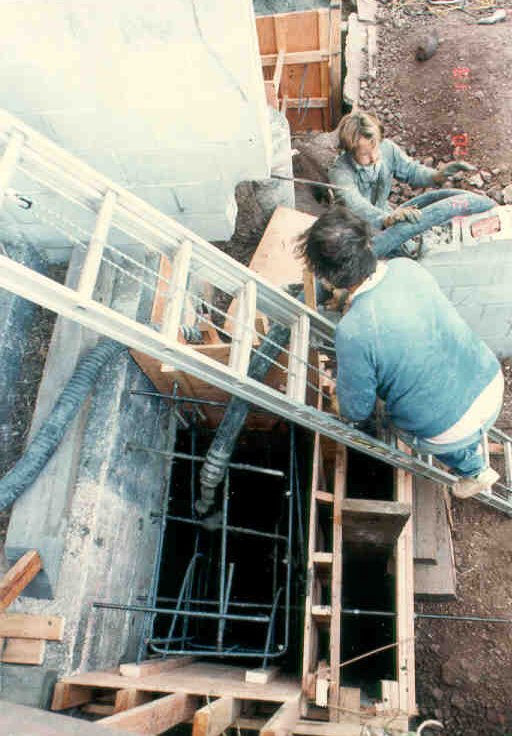
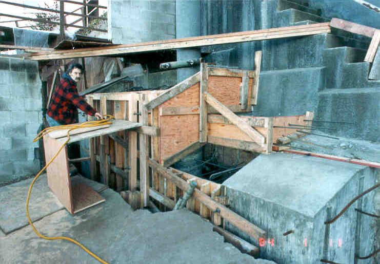
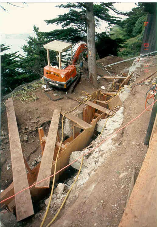
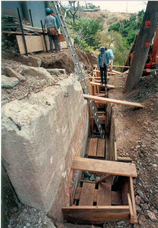
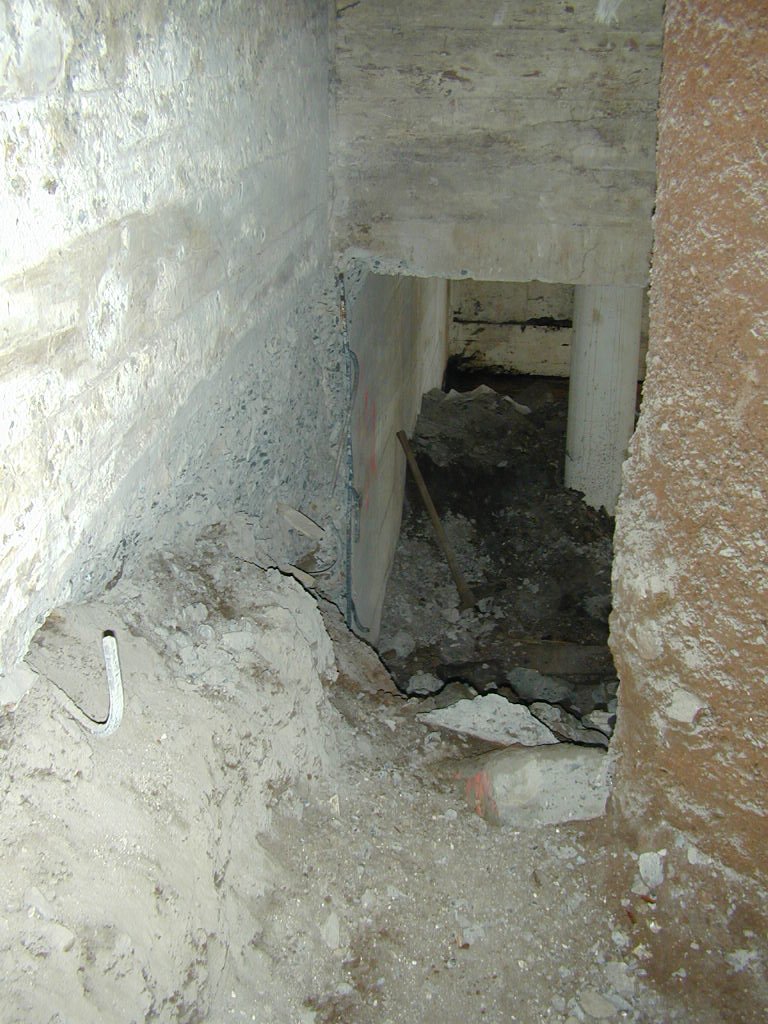
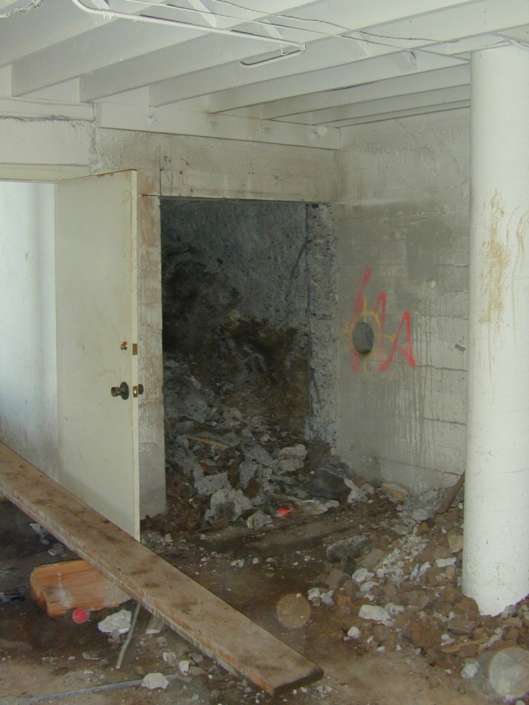
The 1921/1927 foundation was continuously underpinned with skip piers 14+ feet deep interconnected with additional deep piers. During excavation, it was found that the concrete columns (sonotube forned) were founded on shallow bulbs so all of them were underpinned and cast into the reinforced concrete underpinning piers. |
|
 |
 |
 |
 |
Original foundations of what is
now 890 Camino del Mar were formerly
the 1927 extension to 880 Camino del Mar, constructed 1921. In 1941, a permit was issued to underpin the foundations of the building. The 1941 underpinning was hung from the 1927 foundations (because they were founded in loose soil rather than bedrock). In contrast, the 1983 underpinning was socketed deep into the radiolarian chert bedrock; each skip pier and each intermediate pier enclosed the 1941 underpinning and the 1963 foundations in concrete that was vibrated into the bedrock. |
|
 |
 |
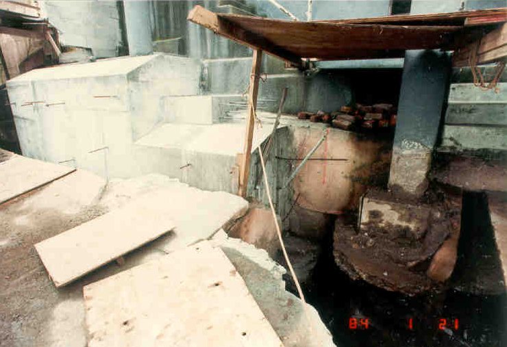 |
Underpinning started in the middle of 890 Camino del Mar and skipped to the east to encompass the bottom of the northeast sonotube formed concrete column along with the steel bracket that had been installed as an emergency procedure to raise and hold back the column which held supported the upper two stories. The columns are grossly.under-reinforced. |
|
|
|
 |
 |
 |
 |
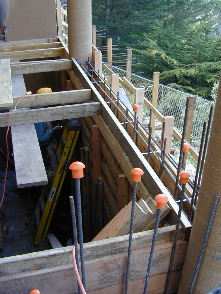
1988 Tieback Retaining Wall |
|
 |
 |
Preliminary seismic/wind strengthening and miscellaneous. From the first image, north elevation (oblique), it can intuitively be seen how important it is to construct the wall between the slender sonotube columns, which are unstable with respect to lateral loading in their current laterally unsupported condition. The higher the level (from the ground surface) the greater the potential for lateral drift (and resulting failure or at least damage) when the ground shakes, so the upper levels, hanging from these very long and slender supports, are hazardous. Good that move-in is not "as-is"; if it was, some emergency cross bracing should be installed. Second image shows lower level windows, west elevation. In addition to seismic/wind, corner column closest to the park and ocean (northwest corner) is cracked and bowing and it is eccentric (outside the corner of the floors above). Replacing the column has been discussed with the Contractor (along with building the new concrete wall) even though the columns will be stiffened by the concrete wall. This corner has to be integrated with the concrete framing in the "game room" (part of the 1927 enlargement) as it is in worse condition than previously seen as the room was filled with the previous owner's storage. There will be continuing appraisal of this issue as underpinning continues as it is a basic stability consideration. 1/17/00 |
|
 |
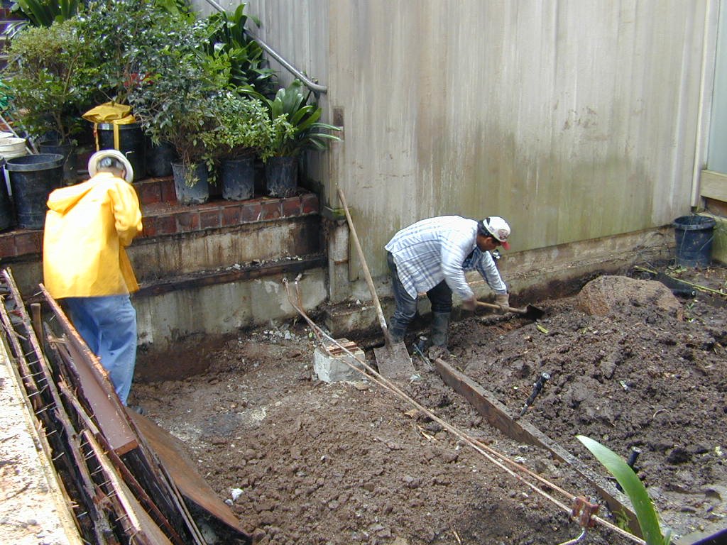 |
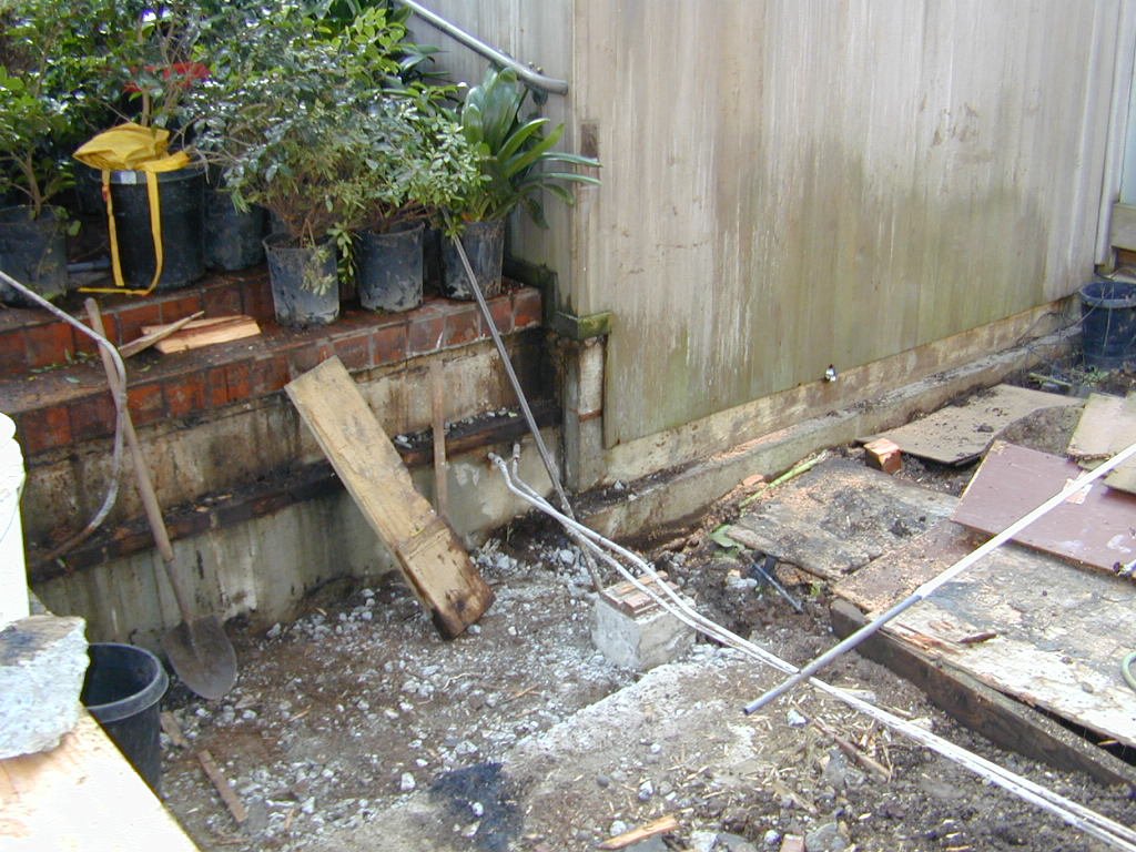
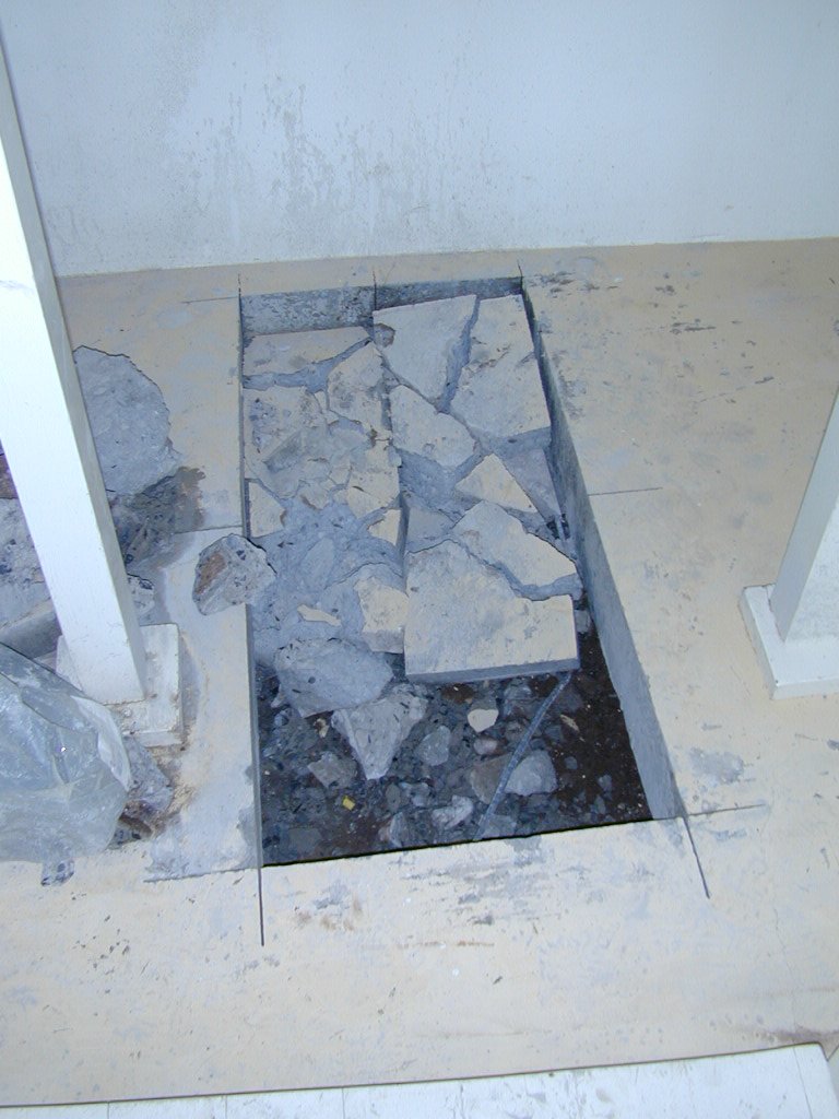
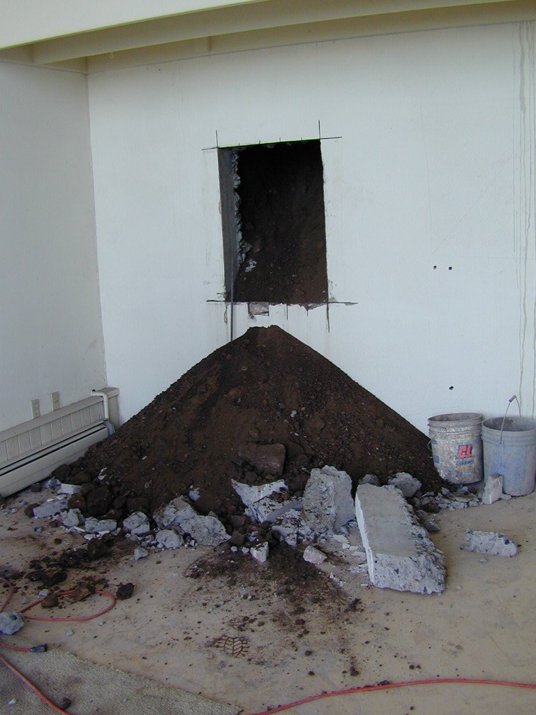
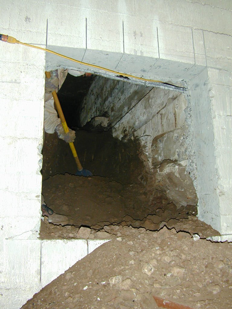
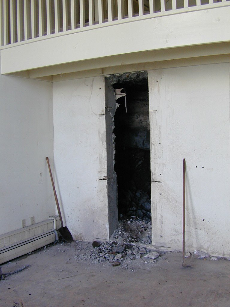
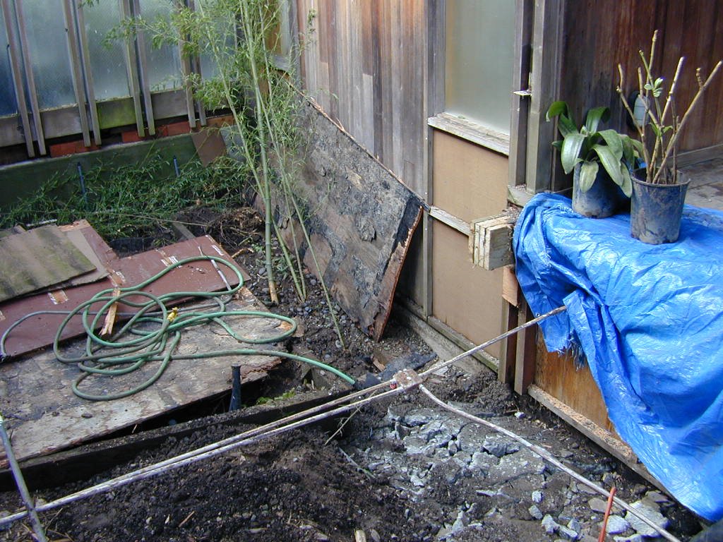
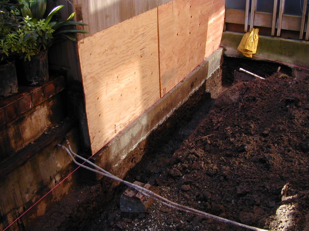
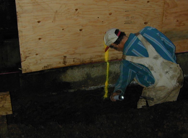
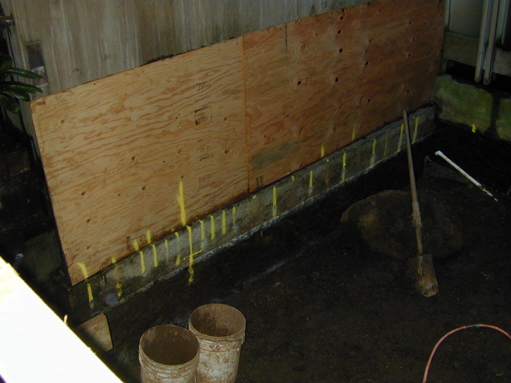
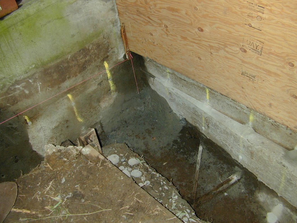
Courtyard: The garage foundations are not on piers; spread footings were merely poured over soil, so to provide vertical resistance to the tieback anchor forces, the foundation (existing footing and new grade beam) will be underpinned at both upper tieback locations. The underpinning pits will be socketed into the radiolarian chert that underlies the surficial soils. Ironically, it appears that the arched 1920's garden walls have held the building at the court level in place all these years even with the pulling of the concrete walls in the "game room" area below (stabilized in 1982 & 1988). Underpinning of the garages will serve to integrate the foundation system via the grade and tie beams, and the new concrete bridge. 1/21/00 |
|
 |
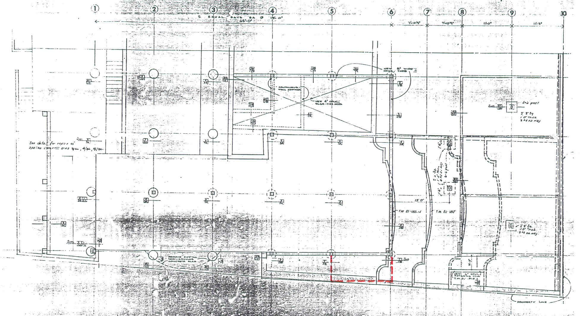 |
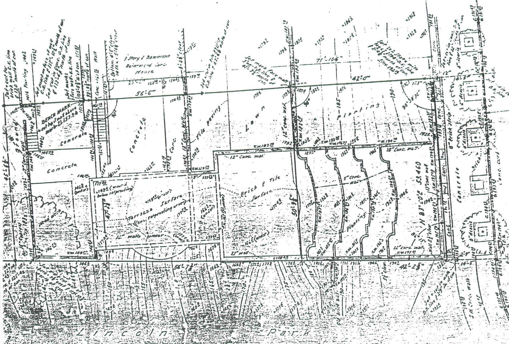
Left image is a Survey of the 1927 garden and
addition
to what was 880 Camino del Mar. Right image is a Foundation Plan for the 1963 residence. The red dashes show extent of breakfast room along Line 5. |
|
|
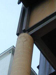
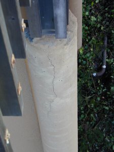
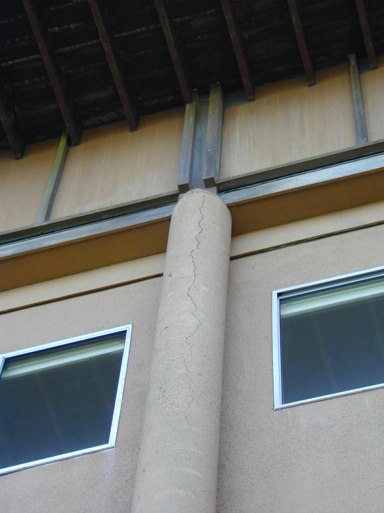
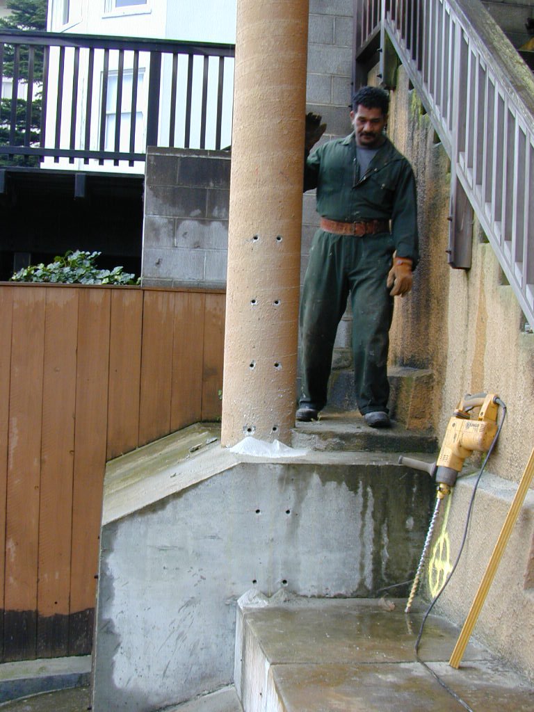
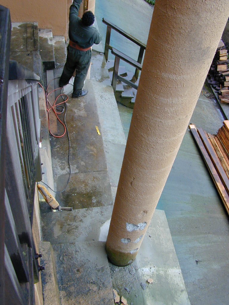
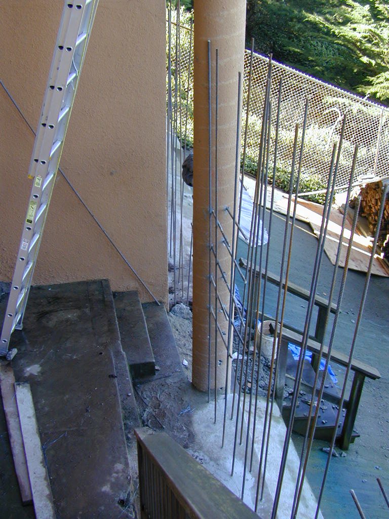
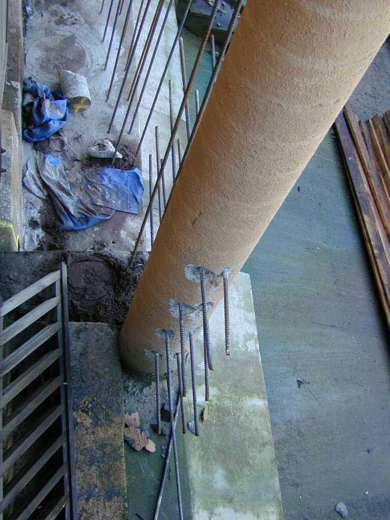
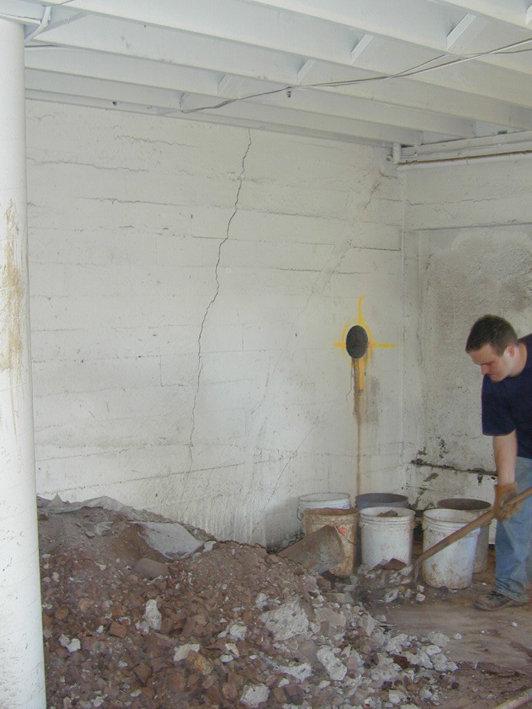
| Slender Columns:
The concrete sonotube columns along the north side are cracked at their heads (below connection to upper two stories that are wood framed). Columns are too slender and upper connection is not "fixed" to resist lateral movement and joint rotation due to sidesway,and they are not recinforced as columns (insufficient reinforcement and confinement). New concrete foundation and new wood wall will stiffen columns but not to the extent that all seismic or wind forces will be transferred to upper stories (mostly glass) without dampening. Along with stiffening and confining of the columns, concrete cracks mayl be epoxy injected to protect reinforcement. |
|
   |
|
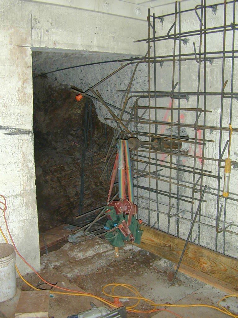
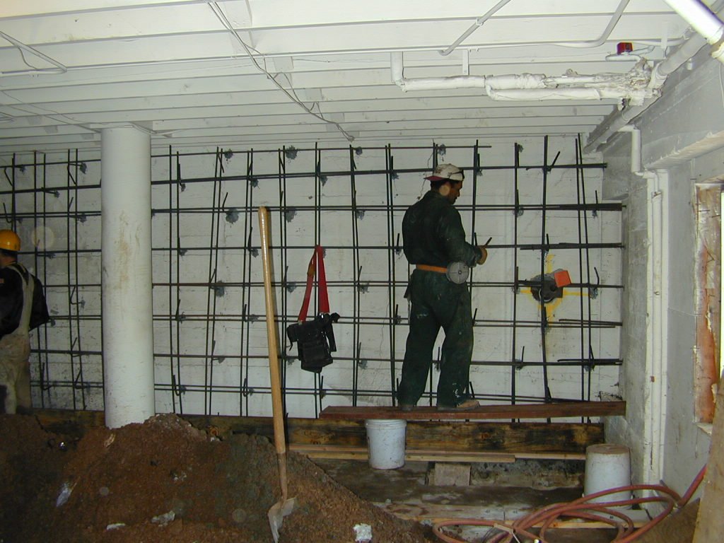
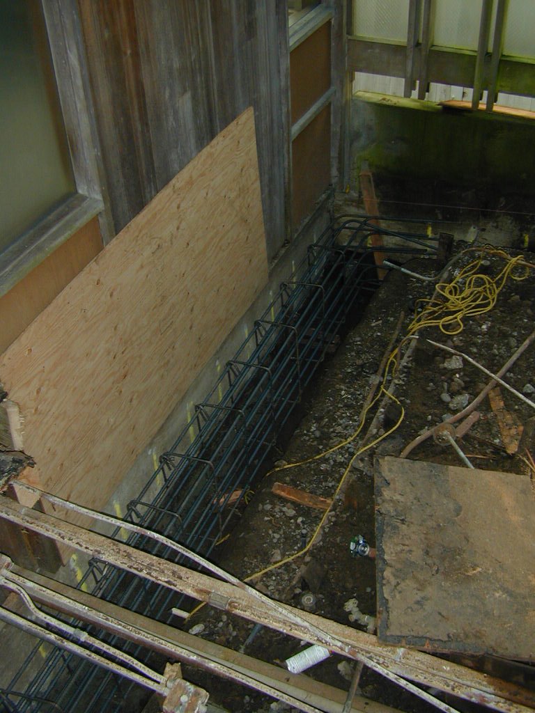
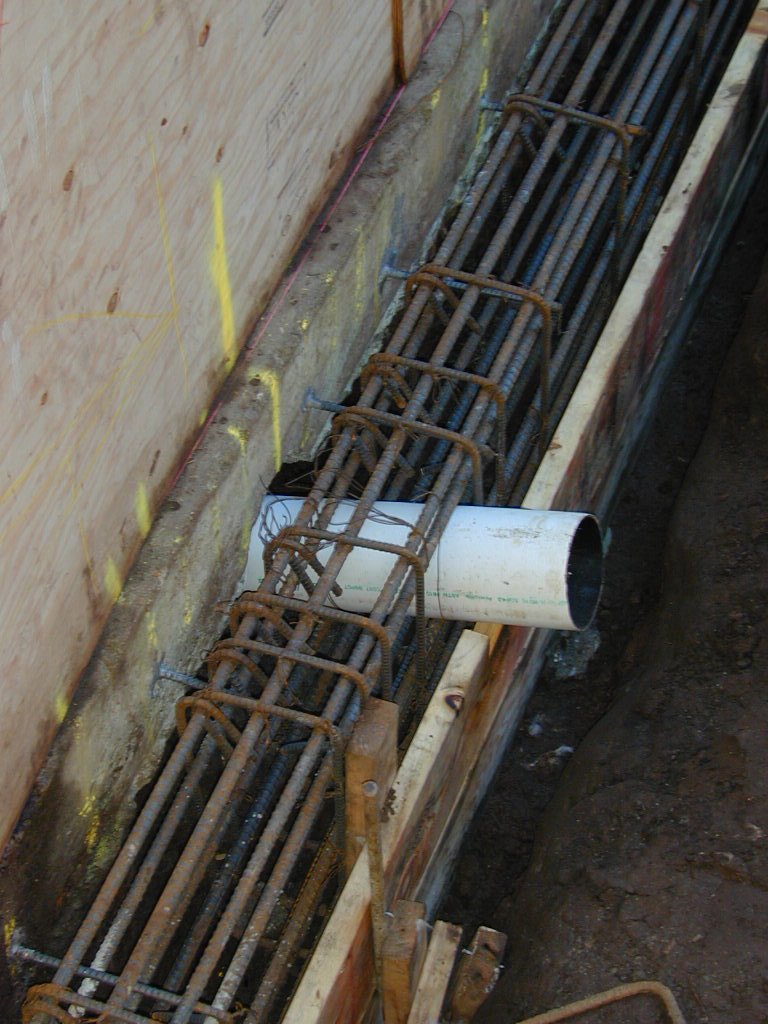
| Lower Tieback Wall: Three post-tensioned double corrosion protected Dywidag tiebacks will be installed through openings cut in the existing lower concrete foundations (underpinned in 1941 & 1983). Tiebacks will extend to anchororage in a new reinforced concrete cross-lot wall that stiffens the slender sonotube concrete columns, also being foundation for a new wood framed wall (office, lower bedrooms, game rm). Framed wall will also vertically/laterally support upper two stories. New foundation wall will integrate/interconnect 1921, 1927, 1963, 1941 & 1983 foundations and 1988 retaining wall. |
    |
    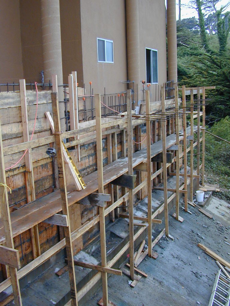  |
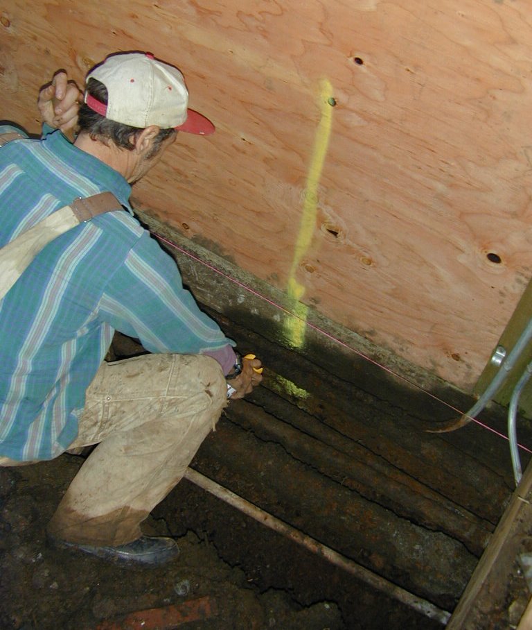
| Middle Tieback Wall: Preparing foundation (1927) for underpinning with new tieback wall (extends across back walls of wine cellar and office). Wall (1963) where concrete is cut (in office area) will be removed when intermedate wall is stabilized. Three postensioned double corrosion protected Dywidag tiebacks will be installed through holes cut in the existing intermediate concrete foundation wall, which is distressed at its western portion. The tiebacks will extend and later be anchored to a new reinforced concrete wall sistered to the existing cross-building wall/foundation at the rear or the office and wine cellar. New wall will integrate and interconnect the 1921, 1927 and 1963 foundations which are presently discontinuous. 2/3/00 |
   |
    |
     |
 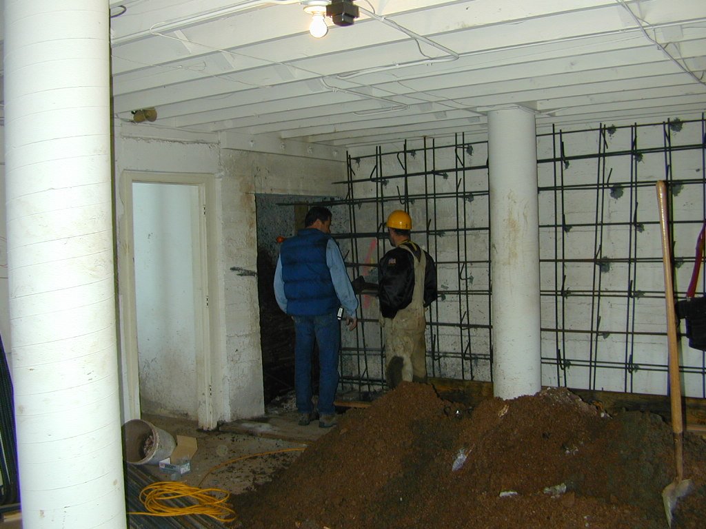  |
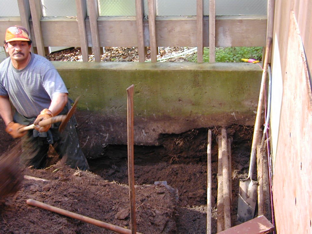
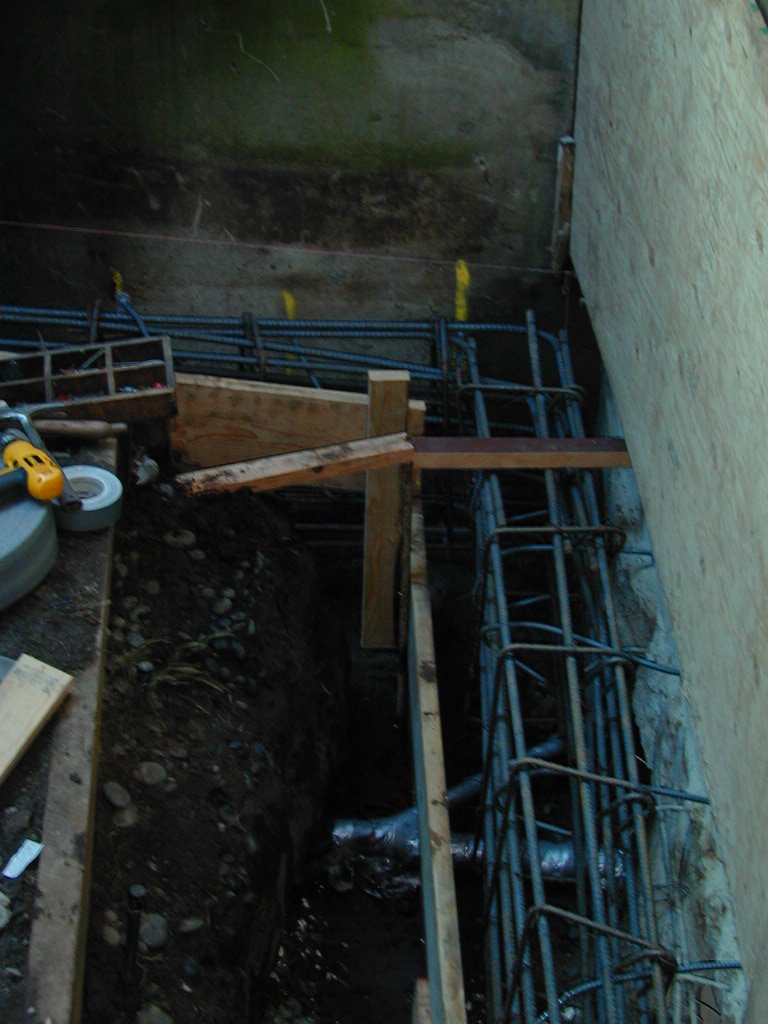
| Intermediate Tieback Wall: The western section of the building is broken up into three levels below the main floor level, and foundation support is compromised by landslide debris that underlys the western foundation. To provide vertical support (for building loads and the vertical component of tieback forces) intersections of transverse walls with the western wall will be underpinned (to depths of 19 and 22 feet). The underpinning, along with the 1927 and 1963 foundations, will be integrated and lateral support will be provided by two tiebacks. |
   |
| Upper Tiebacks at Courtyard: Two postensioned double corrosion protected Dywidag tiebacks, anchored to reinforced concrete ring and bridge in courtyard that integrates garage and residence foundations, will push garage and pull residence foundations. All new reinforced concrete improvements will be interconnected with each other and they will be interconnected with 1921, 1927 and 1963 foundations which are presently discontinuous. In courtyard, tiebacks will be drilled under garages and grouted, and tested, prior to forming and pouring.grade beams that constitute the ring. After the tieback grout and grade beam concrete achieves strength, tiebacks will tensioned and anchored to the upper grade beam portion of the ring. 2/1/00 |
   |
    |
  |
| Courtyard : Layout of stirrup reinforcing. Left is at east tieback, center is at west tieback, and right is at northwest corner (near Breakfast Room) where there is a 1963 pier (which will be chipped into to expose and tie new reinforcing. At tiebacks, shear forces, which induce diagonal tension stresses into the grade beams, must be resisted with closely spaced stirrups (terned "web reinforcing"). |
|
   |
   |